
 EN
EN ES
ES PT
PT RU
RU AR
AR KO
KO MY
MY FIL
FIL BE
BE
How to Select the Perfect AC Compressor & Blower Combo for Your Commercial Fleet
Selecting a commercial fleet AC compressor and blower combo is a system-matching job, not a matter of buying two parts with impressive headline ratings. The compressor must move enough refrigerant at the vehicle's real operating conditions, while the evaporator blower must deliver usable airflow against the resistance of the coil, filters, ducts, and vents. Get that balance wrong and a fleet may see weak pull-down, noisy cabins, evaporator icing, high electrical load, repeated clutch cycling, or premature component replacement.
For buses, trucks, vans, refrigerated vehicles, and mobile equipment, the best combination is the one that meets the heat load without pushing either component outside its practical operating range. This guide gives fleet engineers, converters, procurement teams, and parts distributors a structured way to specify that combination and prepare a quote request that suppliers can answer accurately.
Why the compressor and blower must be selected as one system
The compressor creates refrigerant flow and pressure difference. The evaporator blower moves cabin air across the evaporator coil. They do different jobs, but the passenger experiences only the combined result.
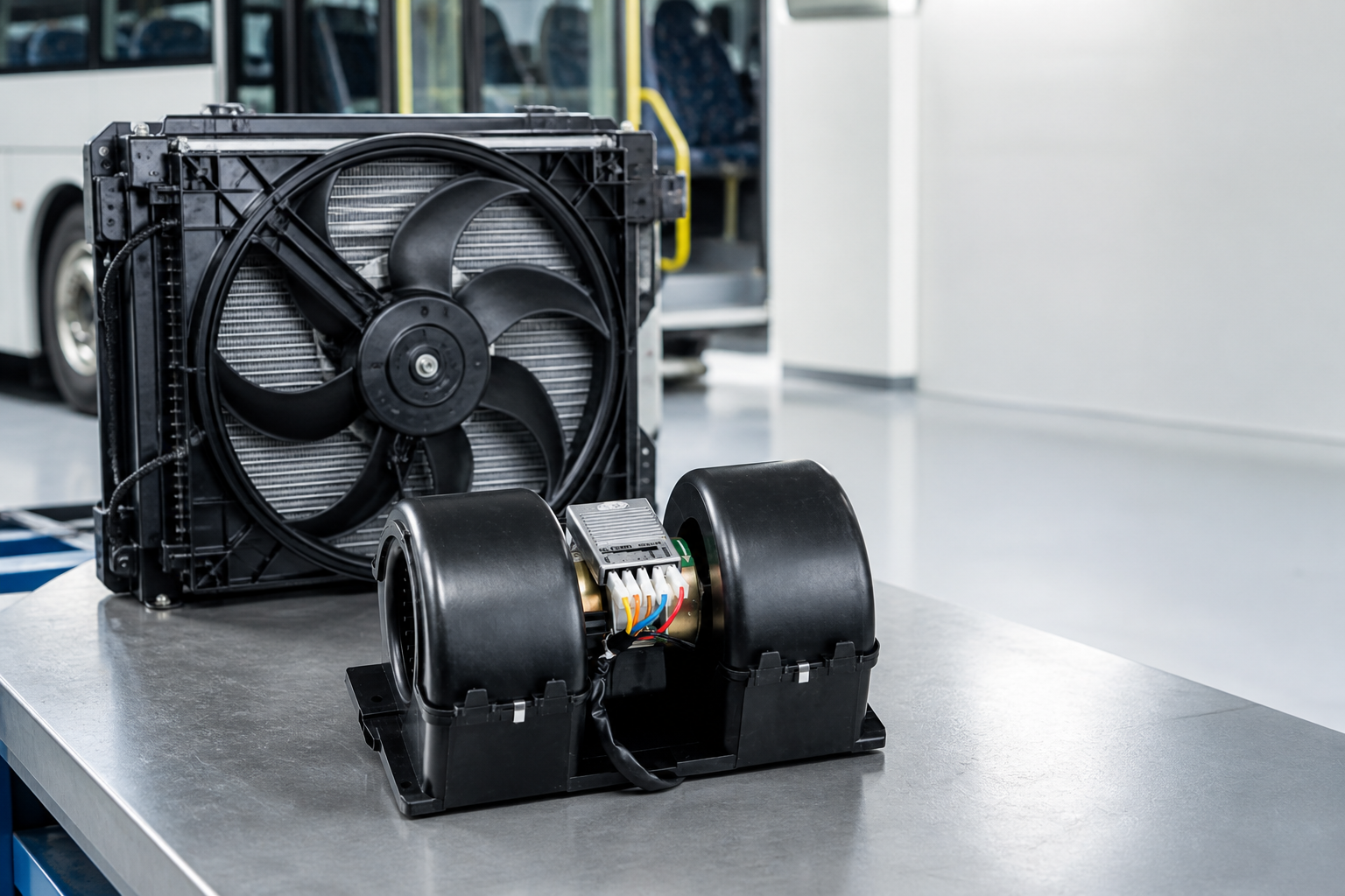
A larger compressor cannot compensate for poor airflow through a restricted evaporator. A high-airflow blower also cannot produce sufficient cooling when compressor capacity falls sharply at idle, at high ambient temperature, or under an unfavorable drive ratio. The condenser fan belongs in the same calculation because inadequate heat rejection raises head pressure and reduces the capacity available at the evaporator.
Practical rule: select the compressor, evaporator blower, condenser fan, coil, ducting, and electrical supply around a shared operating envelope. Do not approve any component from a free-air rating or nominal displacement alone.
Start with fleet duty cycle and heat load
Before comparing part numbers, define what the vehicle actually does. Two vehicles with the same cabin volume may need different systems because one spends its day at highway speed and the other idles with doors opening every few minutes.
| Fleet factor | Why it changes selection | Information to collect |
|---|---|---|
| Vehicle and cabin | Cabin volume, glazing, insulation, passenger count, and equipment create different sensible and latent loads. | Vehicle model, conditioned volume, window area, insulation level, maximum occupants |
| Operating pattern | Idle time and stop-start routes reduce compressor speed and condenser airflow. | Idle percentage, engine-speed range, route profile, door-opening frequency |
| Climate | High ambient temperature and humidity increase cooling demand and condenser pressure. | Design ambient temperature, humidity, solar exposure, altitude |
| Cooling target | Pull-down after parking is a different requirement from maintaining temperature on route. | Starting cabin temperature, target temperature, acceptable pull-down time |
| Service model | Parts commonality and field replacement time may matter more than a small efficiency gain. | Fleet size, depot capability, standard voltages, preferred refrigerant and service parts |
Use a qualified HVAC engineer or system supplier to calculate the design load. For replacements, retain the original system's refrigerant, evaporator, condenser, controls, and compressor limits unless an engineering review supports the change.
Match compressor capacity to the real operating envelope
Compressor selection starts with required cooling capacity, but the catalog capacity must be read at the right conditions. Ask for performance data at the intended refrigerant, evaporating and condensing conditions, compressor speed, and superheat or subcooling assumptions. A single nominal value is not enough for fleet work.
Check capacity at idle and cruise
An engine-driven compressor may look comfortable at cruise speed but struggle during long idle periods. Confirm the minimum compressor speed available at idle, the maximum speed at engine redline, and the proposed pulley ratio. The compressor must remain within the manufacturer's allowable speed range throughout operation.
Confirm drive, clutch, oil, and refrigerant compatibility
Verify mounting pattern, rotation, pulley diameter and groove type, belt alignment, clutch voltage, connector, refrigerant, lubricant, hose ports, and control method. A compressor clutch is not a universal adapter. Weili's public other-parts range, for example, includes application-specific clutch listings for Bitzer/Bock, Hispacold, Thermo King X426/430, and Valeo TM65 units. Buyers should match the exact compressor and pulley specification before ordering.
Review thermal and control protection
Confirm pressure cutouts, evaporator temperature control, clutch cycling logic, and any compressor protection required by the selected model. Reusing incompatible controls can turn a sound mechanical selection into a reliability problem.
Size the evaporator blower by airflow and static pressure
Blower airflow determines how much cabin air crosses the evaporator, but free-air volume is only a starting point. The working point depends on resistance from the evaporator coil, filters, duct length, bends, grilles, and outlet restrictions. Ask the supplier for a fan curve or tested airflow at a stated static pressure whenever it is available.
Weili's evaporator blower range contains 12V and 24V commercial-vehicle options. The ZHF2317 product data provides a useful example of an operating-point specification: test voltage of 27V/13.5V, current no more than 6.0A/14.0A, speed of 3,600 +/- 200 rpm, and airflow of at least 800 m3/h at 100 Pa static pressure. Those numbers are meaningful only when the vehicle duct system is assessed against the same pressure basis.
Translate cabin requirements into blower criteria
- Define required airflow at the vents rather than relying on the blower-outlet value.
- Estimate or measure total external static pressure with the intended coil, filter, ducts, and grilles installed.
- Confirm current draw at system voltage and at each speed setting.
- Check whether the noise target applies at the blower, the duct outlet, or the passenger position.
- Verify orientation, drain clearance, inlet space, motor cooling, connector, and mounting points.
For a replacement project, measure voltage and current on a healthy vehicle and compare vent airflow before removing the original component. Those field readings give the supplier a far better target than an old part number alone.
Balance condenser airflow with compressor demand
The condenser must reject cabin heat plus compressor work. When a bus or truck idles, ram air falls away and the condenser fan carries more of the load. A high-capacity compressor paired with inadequate condenser airflow may run at elevated pressure, cycle frequently, or deliver disappointing cooling in traffic.
Weili's condenser and axial fan category includes brushed and 24V BLDC options for bus air-conditioning systems. The LNF2201W listing specifies 26V test voltage, current no more than 13.5A, and airflow of at least 2,500 m3/h at 100 Pa. Treat this as a component operating point, then verify that the condenser core, shroud, fan quantity, and installation produce the required heat rejection on the vehicle.
Shroud sealing matters. Air that recirculates around the fan or bypasses the condenser core does not help the system, even when the fan's catalog airflow looks adequate.
Protect the vehicle's 12V or 24V electrical architecture
Electrical fit is a hard constraint for commercial fleets. Add the evaporator blower, condenser fans, compressor clutch or electric compressor, controls, and other continuous loads. Then review wiring, relays, fuses, connectors, alternator output, battery capacity, and voltage drop at the actual operating current.
Electrical checks before approval
- Nominal system voltage and allowed operating-voltage range
- Continuous current at the selected speed and pressure point
- Starting or inrush current where applicable
- Voltage measured at the component under load
- Wire gauge, connector rating, relay rating, and fuse coordination
- Alternator margin at idle with lights, doors, charging equipment, and accessories active
Do not assume a 24V label makes two products electrically compatible. Commercial charging systems may operate above nominal voltage; use the supplier's specified test and operating range.
Use a selection matrix instead of comparing labels
| Decision point | Compressor evidence | Blower/fan evidence | Fleet acceptance check |
|---|---|---|---|
| Cooling at worst case | Capacity map at stated refrigerant, speed, and temperatures | Airflow at stated static pressure | Pull-down and stabilized cabin-temperature test |
| Idle performance | Capacity at idle compressor speed | Condenser airflow with no ram air | Stationary high-ambient test |
| Electrical load | Clutch or electric-compressor current | Current at selected speed and pressure | Voltage-drop and alternator-margin test |
| Mechanical fit | Mount, pulley, ports, rotation, envelope | Envelope, inlet clearance, orientation, mounting | Prototype installation and service-access review |
| Lifecycle support | Model traceability and service parts | Motor/fan replacement path and connector consistency | Depot spares and replacement-time review |
Validate the combo on a representative vehicle
Paper selection narrows the field. Vehicle testing closes the decision. Install the proposed combination on a representative unit and test the conditions that cause the fleet trouble. Do not limit validation to a mild day in the workshop.
- Record ambient temperature, humidity, solar exposure, passenger or simulated heat load, and vehicle starting condition.
- Measure cabin and vent temperatures over time, including pull-down and stabilized operation.
- Record high- and low-side pressures using the service procedure appropriate to the system.
- Measure compressor speed, blower voltage/current, condenser-fan voltage/current, and voltage drop.
- Check evaporator icing, condensate drainage, clutch cycling, belt behavior, noise, vibration, and connector temperature.
- Repeat at idle and representative road speed.
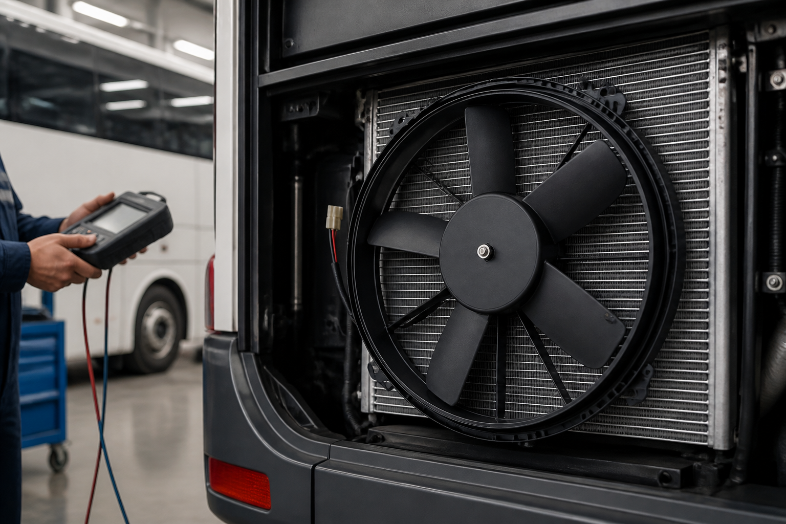
For a multi-model fleet, validate the highest-load or most constrained configuration first, then confirm that the same component set does not create noise, overcooling, or packaging problems in smaller vehicles. Weili's published application coverage spans buses, automobiles, heavy transport, and large vehicles, which makes the vehicle details in the inquiry especially important.
Qualify the supplier as carefully as the components
Fleet downtime is often caused by specification drift, unavailable replacements, or incomplete application data rather than by the original sizing calculation. Ask potential suppliers how they control model revisions, confirm operating points, identify production batches, and support repeat orders.
Useful supplier evidence includes dimensional drawings, wiring details, test conditions, inspection records, packaging information, sample availability, warranty terms, and a defined process for handling field failures. Verify each item for the exact model under consideration. The Weili company profile identifies the business as an automotive air-conditioner fan manufacturer integrating research, production, and trade; procurement teams should still request model-specific documents for the fleet program.
Send a quote package that prevents mismatching
A useful RFQ lets the supplier evaluate the complete operating envelope. Include:
- Vehicle make, model, year, engine, fleet quantity, and target service life
- Cabin dimensions, passenger count, insulation, glazing, and route profile
- Design ambient conditions and required pull-down or temperature-maintenance target
- Refrigerant, compressor model or required capacity map, speed range, pulley, clutch voltage, ports, and mounting drawing
- Evaporator coil details, duct layout, estimated static pressure, required vent airflow, and noise target
- Condenser core, fan quantity, mounting arrangement, shroud, and idle cooling requirement
- System voltage, alternator output at idle, available current, connector, fuse, and control method
- Photos, current part numbers, failure history, sample quantity, annual demand, destination, and documentation needs
Discuss your fleet's airflow and component match
Send Weili your vehicle voltage, evaporator resistance or target static pressure, required airflow, condenser arrangement, current compressor information, and annual quantity. The team can review relevant blower, condenser-fan, motor, or clutch options for your application.
Request a fleet component reviewCommon selection mistakes to avoid
- Buying by displacement or free-air volume: neither value describes the installed operating point.
- Ignoring idle conditions: stop-start fleets often have their weakest compressor and condenser performance when cooling demand is highest.
- Upsizing only one component: more compressor capacity can increase condenser demand, while more blower airflow can raise noise and electrical load.
- Matching voltage but not current: connectors, relays, wiring, and alternator margin must carry the real load.
- Skipping fit and service access: a component that fits the envelope may still block belt adjustment, filter replacement, drain routing, or connector access.
- Ordering a clutch by compressor family alone: pulley diameter, groove, voltage, mounting, and exact compressor variant must all agree.
FAQ
Can I select a blower from its maximum airflow rating?
No. Use airflow at the static pressure created by the installed evaporator, filter, ducts, bends, and grilles. A free-air rating can overstate the airflow available at the vents.
Should I oversize the AC compressor for faster pull-down?
Only after checking the complete system. Extra compressor capacity may exceed condenser, evaporator, drive, control, or electrical limits. Compare performance maps at idle and cruise, then validate the proposed system on the vehicle.
Is a 24V compressor clutch compatible with any 24V fleet?
No. Confirm operating-voltage range, coil current, connector, pulley diameter and groove, mounting, compressor model, and control circuit. Nominal voltage is one item in the compatibility check.
When should a fleet consider a brushless condenser fan?
Consider it when the application benefits from electronic speed control, reduced brush maintenance, or a specific noise and duty-cycle target. Compare the exact fan's airflow at pressure, current draw, controller requirements, protection, and replacement strategy rather than choosing by motor type alone.
What is the fastest way to obtain an accurate supplier recommendation?
Send the vehicle duty cycle, design climate, electrical limits, compressor and refrigerant data, target airflow at static pressure, mounting drawings, photos, current part numbers, and annual quantity. A complete operating-point package prevents several rounds of clarification.
The right commercial fleet AC compressor and blower combo is defined by measured performance on the vehicle. Specify the operating envelope, compare components at common conditions, verify mechanical and electrical fit, and approve the package only after representative testing.